Saturday, February 2, 2008

"Ohmmeter,ammeter and multitester"

Ohmmeter:
Photobucket
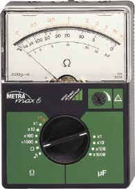
  • An ohmmeter is an electrical instrument that measures electrical resistance, the opposition to the flow of an electric current. Microohmmeters make low resistance measurements. Megaohmmeters measure large values of resistance.
    The original design of an ohmmeter provided a small battery to apply a voltage to a resistance. It used a galvanometer to measure the electric current through the resistance. The scale of the galvanometer was marked in ohms, because the fixed voltage from the battery assured that as resistance decreased, the current through the meter would increase.

Ammeter:

  • An ammeter is a measuring instrument used to measure the flow of electric current in a circuit. Electric currents are measured in amperes, hence the name. The word "ammeter" is commonly misspelled or mispronounced as "ampmeter" by some.
    The earliest design is the D'Arsonval galvanometer or moving coil ammeter. It uses magnetic deflection, where current passing through a coil causes the coil to move in a magnetic field. The voltage drop across the coil is kept to a minimum to minimize resistance across the ammeter in any circuit into which it is inserted.

Multitester:
  • Photobucket

"Electric Symbols"


Batteries, single cell, multi-cell

Capacitor

Capacitor, polarized

Capacitor, variable

Diode

Zener diode

Tunnel diode

LED

Photodiode

Silicon-controlled rectifier

Varicap

Schottky diode

Fuse, IEC (upper) and American (lower two)]]

Inductor

Operational amplifier

Phone jacks

Potentiometer

Resistor IEC and American versions

Switch, SPDT

Switch, DPDT

Transformer, with center tap

NPN transistor

Field-effect transistor

Vacuum tube diode

"Oersted and Faraday"

"Oersted and Faraday"
Photobucket
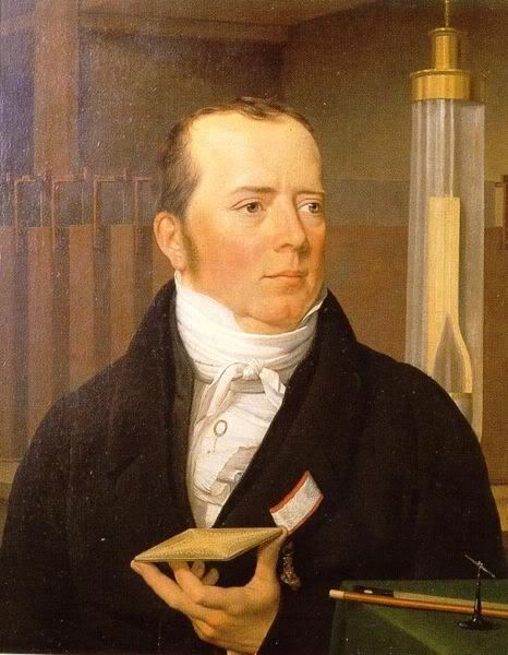
  • Hans Christian Ørsted (August 14, 1777March 9, 1851) was a Danish physicist and chemist. He shaped post-Kantian philosophy and advances in science throughout the late nineteenth century.[1] He is best known for discovering the relationship between electricity and magnetism known as electromagnetism.
  • Ørsted developed his interest in science while working as a young boy for his father, Søren Christian Ørsted, who owned a pharmacy. He and his brother, Anders Sandøe Ørsted, received most of their early education through self-study at home, leaving home for Copenhagen in 1793 to take entrance exams for the University of Copenhagen. The brothers passed and distinguished themselves academically at the University. By 1796, Ørsted received honours for his papers in both aesthetics and physics.
    In 1801, Hans received a travel scholarship and public grant that enabled him to spend three years traveling in Europe. In Germany, he met Johann Wilhelm Ritter, a physicist who believed there was a connection between electricity and magnetism. The connection made sense to Ørsted since he believed in the unity of nature, and, therefore, that a relationship must exist between most natural phenomena.
    Their conversations drew Ørsted into the study of physics. He became a professor at the University of Copenhagen in 1806 and continued his research with electric currents and acoustics. Under his guidance, the University developed a comprehensive physics and chemistry program and established new laboratories.
  • While preparing for an evening lecture on 21 April 1820, Ørsted developed an experiment which provided evidence that surprised him. As he was setting up his materials, he noticed a compass needle deflected from magnetic north when the electric current from the battery he was using was switched on and off. This deflection convinced him that magnetic fields radiate from all sides of a wire carrying an electric current, just as light and heat do, and that it confirmed a direct relationship between electricity and magnetism.
    At the time of discovery, Ørsted did not suggest any satisfactory explanation of the phenomenon, nor did he try to represent the phenomenon in a mathematical framework. However, three months later he began more intensive investigations. Soon thereafter he published his findings, proving that an electric current produces a magnetic field as it flows through a wire. The CGS unit of magnetic induction (oersted) is named in honor of his contributions to the field of electromagnetism.
    His findings resulted in intensive research throughout the scientific community in electrodynamics. The findings influenced French physicist André-Marie Ampère's developments of a single mathematical form to represent the magnetic forces between current-carrying conductors. Ørsted's discovery also represented a major step toward a unified concept of energy.

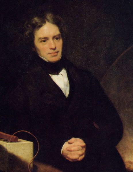
Michael Faraday:

Photobucket

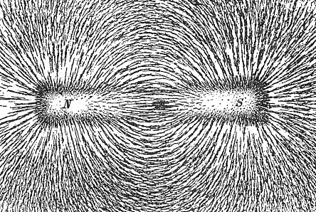
"Magnetic Field"

"Magnetic Field"

Photobucket

"Ohm's Law"

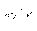
Ohm's Law

I=V/R

  • where I is the current in amperes, V is the potential difference between two points of interest in volts, and R is a circuit parameter, measured in ohms (which is equivalent to volts per ampere), and is called the resistance. The potential difference is also known as the voltage drop, and is sometimes denoted by U, E or emf (electromotive force) instead of V.[1]
    The law was named after the physicist Georg Ohm, who, in a treatise published in 1827, described measurements of applied voltage, and current passing through, simple electrical circuits containing various lengths of wire, and presented a slightly more complex equation than the one above to explain his experimental results. The above equation is the modern form of Ohm's law; it could not exist until the ohm itself was defined (1861, 1864). Well before Georg Ohm's work, Henry Cavendish found experimentally (January 1781) that current varies in direct proportion to applied voltage, but he did not communicate his results to other scientists at the time.[2]
    The resistance of most resistive devices (resistors) is constant over a large range of values of current and voltage. When a resistor is used under these conditions, the resistor is referred to as an ohmic device because a single value for the resistance suffices to describe the resistive behavior of the device over the range. When sufficiently high voltages are applied to a resistor, forcing a high current to flow through it, the device is no longer ohmic because its resistance, when measured under such electrically stressed conditions, is different (typically greater) from the value measured under standard conditions (see temperature effects, below).
    Ohm's law, in the form above, is an extremely useful equation in the field of electrical/electronic engineering because it describes how voltage, current and resisitance are interrelated on a macroscopic level, that is, commonly, as circuit elements in an electrical circuit. Physicists who study the electrical properties of matter at the microsopic level use a closely related and more general vector equation, sometimes also referred to as Ohm's law, having variables that are closely related to the I, V and R scalar variables of Ohm's law, but are each functions of position within the conductor.

Photobucket

"Electric Current"

"Current"

  • Electric Current is the flow (movement) of electric charge. The SI unit of electric current is the ampere (A), which is equal to a flow of one coulomb of charge per second
  • The amount of electric current (measured in amperes) through some surface, e.g., a section through a copper conductor, is defined as the amount of electric charge (measured in coulombs) flowing through that surface over time. If Q is the amount of charge that passed through the surface in the time t, then the average current I is:

I=Q/T

  • By making the measurement time T shrink to zero, we get the instantaneous current i(t) as:

i(t)=dQ/dT

  • The ampere, the measure of electric current, is an SI base unit so that the coulomb, the measure of electric charge, is derived from the definition of the ampere.

Photobucket

ChatBox